Over the last four months I have been experimenting extensively with various hop up modifications. From the flat hop to the R-Hop and a little bit of everything in between. My personal quest for the ultimate in accuracy has lead me to believe the R-Hop generally offers the most optimal performance / cost ratio for most setups. There are several truly specialized hop up modifications that perhaps gain the slight edge, but they are held back by their maintenance heavy requirements and difficulty of install – especially doing it properly the first time, and often the first time is the only time you have as they are rather permanent modifications.
With the proper tools at hand, an R-Hop can be generally fitted and installed in under 15 minutes. With the Z-Kit, it can be done even faster. That being said, an R-Hop isn’t always the best choice for a particular end-user. As a do-it-yourself type, you may not find it particularly easy or patience-inspiring to install one. Furthermore, they can be expensive depending on where you source your contact patches from. I’ve also noted they require a bit more tuning to reach the “sweet spot” as opposed to a traditional hop up bucking and nub assembly. Certain barrels do not accept R-Hops very well. With some that feature very small hop up chamber windows, you may find the R-Hop contact patch has to be profiled to the point where it is too weak – consequently leaving your hop up turned “on” can temporarily or permanently deform the contact patch and/or dislodge it causing untold accuracy issues. Lastly, I bring up the issue of tools. Without the right tools, the job becomes all the more harder to accomplish. You can certainly fudge your way through it with some rudimentary tools, but good tools are obviously worth their weight in gold.
So for individuals who may not have the time, tools, money or patience to perform an R-Hop installation, yet still want more ‘oomph’ over a stock hop up bucking, what might they consider?
The Hybrid Hop Up
I consider the definition of a hybrid hop up a cross between a traditional hop up and the specialized hop ups. It can borrow features from either, and is generally a good ‘compromise’ in that it will typically gain you better performance than a traditional hop up yet not be as intensive an install or maintenance inducing as a specialized one. Most of the time, hybrid hop ups are a mash-up of custom hand fitting and commercially available pieces. A good example of a full fledged commercially produced hybrid hop up might be the RTX Maple Leaf.
One such method I have been experimenting with is the pairing of an M-Nub with a standard hop up bucking. As noted in our Z-Kit review, the M-Nub requires minor modification to the hop up arm assembly to make it work. About the only tools required is a means of accessing your hop up chamber, a razor blade, and a good file. Installation can be accomplished in 5 minutes or less. In quick summary, all that is needed is to size it to fit your hop up window, create a flat surface on your hop up arm, and affix the M-Nub. It’s that easy.
As for which hop up bucking one should use – that depends mostly on personal preference. I would note that it seems to perform best with anything less than 70 degrees hardness, though. The harder buckings do not lend themselves very well for conformation around the BB like the softer ones do. As the M-Nub is made from fairly soft and pliable material, so too should your bucking choice be. My personal preference is for the M-Nub and Prometheus Purple combination. Real Sword and Guarder Clear buckings work very well too. KWA buckings, of course, blow chunks.
Performance wise I’ve found that this combination is especially well suited for enhancing short-barreled AEG’s – though I have used it on up to 450mm length barrels. Coupled with standard barrel lockdown techniques, my 208mm 6.03 TBB (8.1″ for the metric-adverse) with the above hop up combination has encountered little trouble slinging plastic against AEG’s sporting longer barrels. In fact, it has often out-ranged them, as noted by a few observers during the last airsoft OP: “Damn that thing has some serious throw!”
As a Version 3 gearbox owner, you may have noticed that occasionally you get an odd selector switch problem now and then out of your AK. Granted, these instances are rare and far between, but to the uninitiated they can be frustrating to track down and properly diagnose. This article will show you a few things to look out for. We will also delve just a bit into the trigger switch assembly too, as that is part of the system.
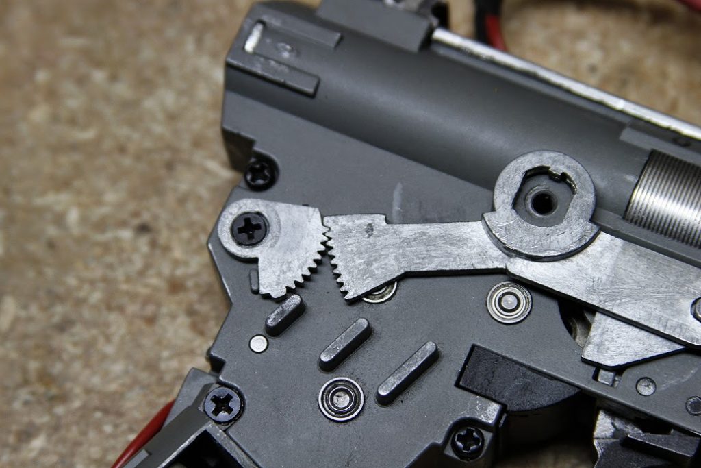
Internal selector switch gears. The exterior selector switch interfaces with the assembly on the right.
Before attempting to diagnose your selector switch issues, first determine whether or not you are operating with a fully charged battery. While this seems rather obvious, it is fairly common for folks to overlook this part, and futilely exclaim their gun is broken when it is a simple matter of a dead battery.
As we are working from the outside in on this guide, after you determine your battery is fine, look immediately at the external selector switch for damage. Occasionally during a game, you might suddenly notice that your external selector switch is stuck and is unable to move from its current position. Before you panic, remove the dust cover and take a peak inside the receiver at the internal selector gears as pictured above. A few things can jam these up and prevent their movement, and one of those is debris or BB’s. If you reload with your muzzle pointed skyward and your mags do not have the last round feed feature, you can occasionally get BB’s rolling backwards inside the receiver. Sometimes one of these will get stuck in between the teeth of the selector gears and jam them. This is a pretty rare problem, but I’ve seen it happen to a number of guns. The quick fix is to simply pop out the jammed BB and get back into the game. Depending on how badly the BB is stuck in there, you may or may not have to remove your gearbox from the receiver to dislodge it.
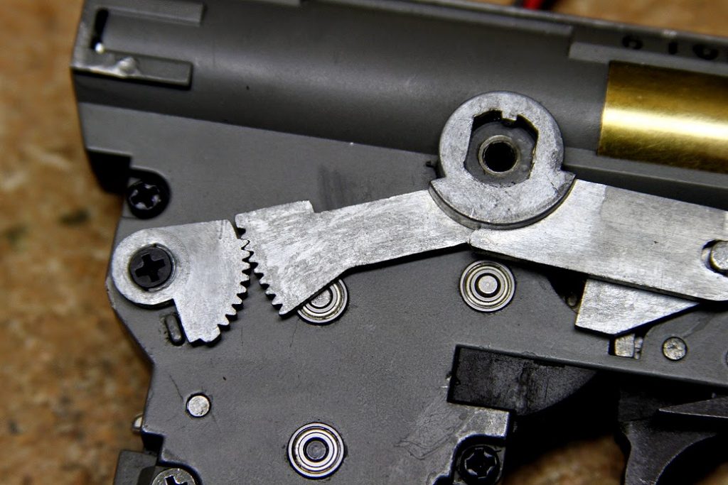
Adjusting a worn selector switch.
Another problem with regard to the external and internal selector switches can be attributed to “slop” or being worn out, or even built out of spec. Generally slop or wearing out doesn’t occur, except in situations where the gun has been heavily used. You can usually spot slop by slipping the selector switch to the semi-auto position and then slowly (with the top cover removed) examine its travel as you slide it upwards into the full auto position. If while observing this you see that the internal selector gears have not moved, then you have evidence of “slop.” With slop, you might have noticed that this is why your AEG no longer works correctly on full auto when it is engaged in the full auto slot. You may also notice that if you push the selector switch just a touch higher, to where it rests just above the full auto notch, that you can usually engage the full auto mode. If this is the case, either your external selector is out of spec, worn out, or the internal selector switch gears are worn out. More particularly, the worn out section is where the external selector switch fits into the internal selector gear.
One potential fix is to simply move the internal selector switch up exactly one gear tooth (as pictured above.) With AEG’s that have out of spec or very worn exterior selector switches, this has solved 99% of the problems I encounter. Be warned: on a brand new or lightly used AEG, doing this can mean that your semi-auto position is now a full auto position! For guys who want their AEG’s to strictly shoot full auto only on both selector switch positions, you could conceivably do this. Be sure to fully test for proper function if you mess with the selector switch gears.
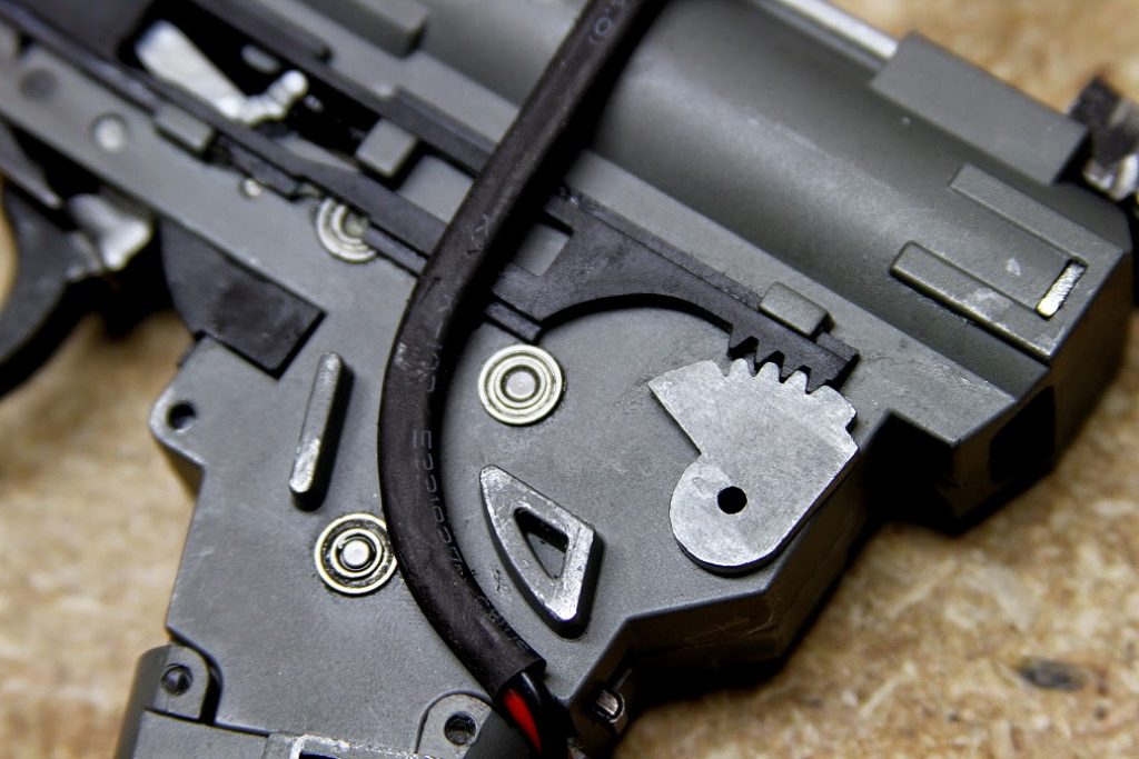
Selector plate and selector gear meshing.
Keeping in mind that we are working on the internal selector gears, you should take the time to also examine them for broken or damaged teeth. If this is the case, you could be experiencing slippage or incorrect meshing – which can cause a variety of issues such as inadvertent full auto in the semi-auto mode, failure to engage in the correct fire mode, or simply not working.
This also applies to the left side of the gearbox and the selector switch plate (the plastic part.) On a Version 2 gearbox, a stripped selector plate is usually the most common issue I’ve encountered. On a version 3, I have yet to see a stripped selector plate, but it is a good idea to examine this area while you’re digging around.
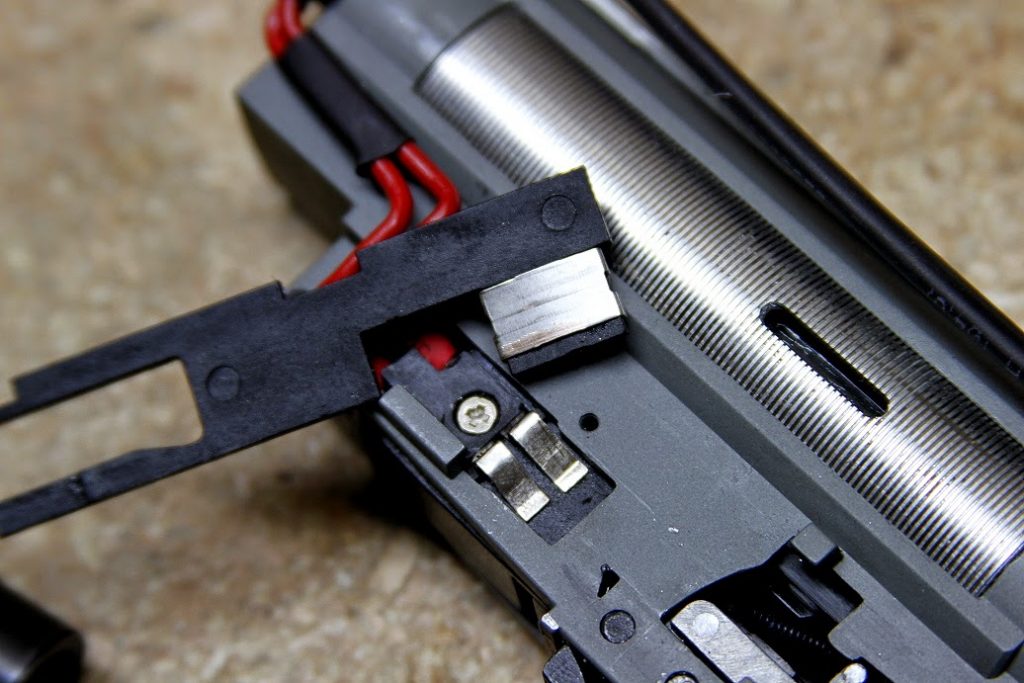
Selector switch plate trigger contact surface.
Removing the selector plate next, we will be looking at the trigger contact surface for damage or burn-through. Again, not a real common problem. If you’re shooting an extremely high ROF AEG with heavy duty LIPO’s with a high C rating you might see this area burned out. Typically, however, the most you might see is some slight wear and maybe a bit of carbon buildup. You can scrape the carbon off with a razor blade.
It’s also a good idea to make sure the selector switch plate can move freely in its track and that nothing is binding or preventing it from moving properly. On some gearboxes I’ve examined, there can be some issues with it dragging badly against the trigger return spring that pokes out of the triangular notch on the left side. Sometimes if these springs have been replaced or are incorrect, they can be slightly too long and thus hit the selector switch plate. You can either trim the spring to correct length so it sits flush with the gearbox, or simply radius the corner of the selector switch plate that hits the spring. Doing the latter is sometimes the more preferable and quicker option.
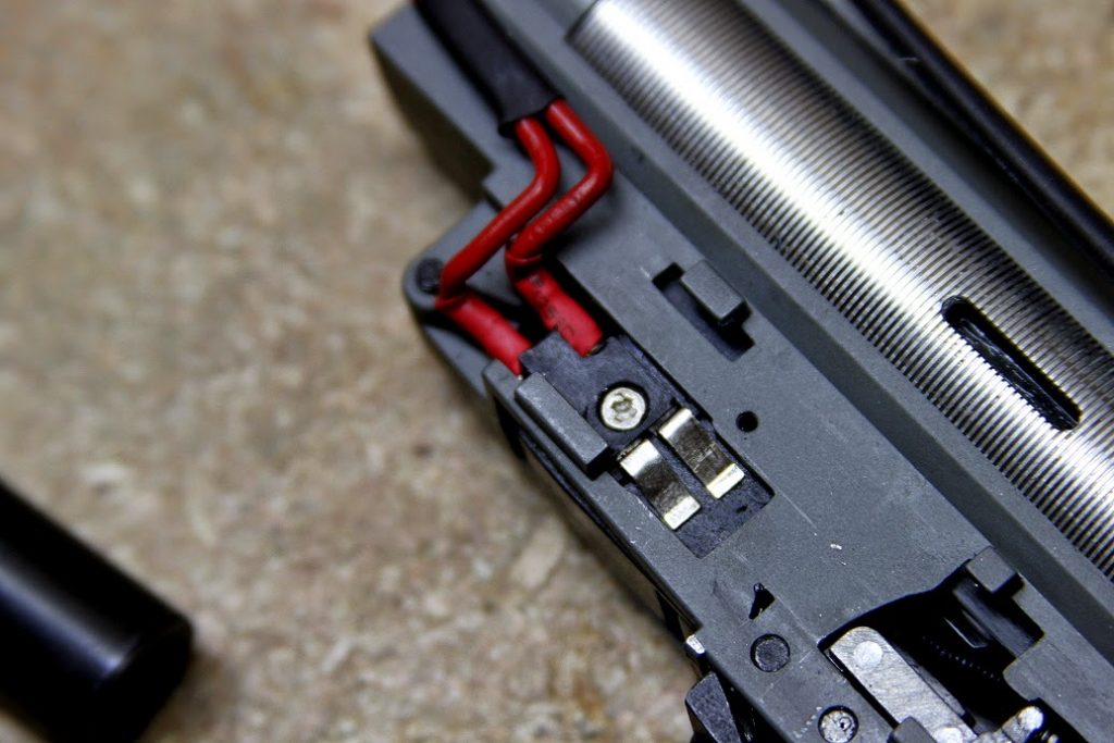
Trigger contact tabs.
Next we are taking a look at the trigger contact switch. Most Version 3 designs have a dual contact system – basically two tabs that engage the trigger switch plate and complete an electric circuit. These tabs, like on any AEG can wind up deformed with time and heavy use. If this happens, they don’t aren’t necessarily making 100% contact with the trigger switch plate, which can result in a non-firing condition.
There are three ways of fixing this:
Method #1 is to slightly bend or flex the tabs upwards, away from the gearbox body so they can make full contact with the selector switch plate. The biggest problem with this method is the tabs are very fragile, and if you bend them up too much, you can risk breaking them off. In which case you’ll be looking at a new trigger switch or scrounging for new contacts in your box-o’-scrap-parts.
Method #2 is to build up the surface just a bit with silver solder. Some guys like to “bridge” both contacts with solder as well. This design, in fact, is what is found on the semi-auto-only SVD. The biggest thing to pay heed with when soldering the contacts is it has to be done just right. Too much solder and you can cause excessive friction and binding with your selector switch plate – sometimes even preventing it from sliding over the contacts entirely!
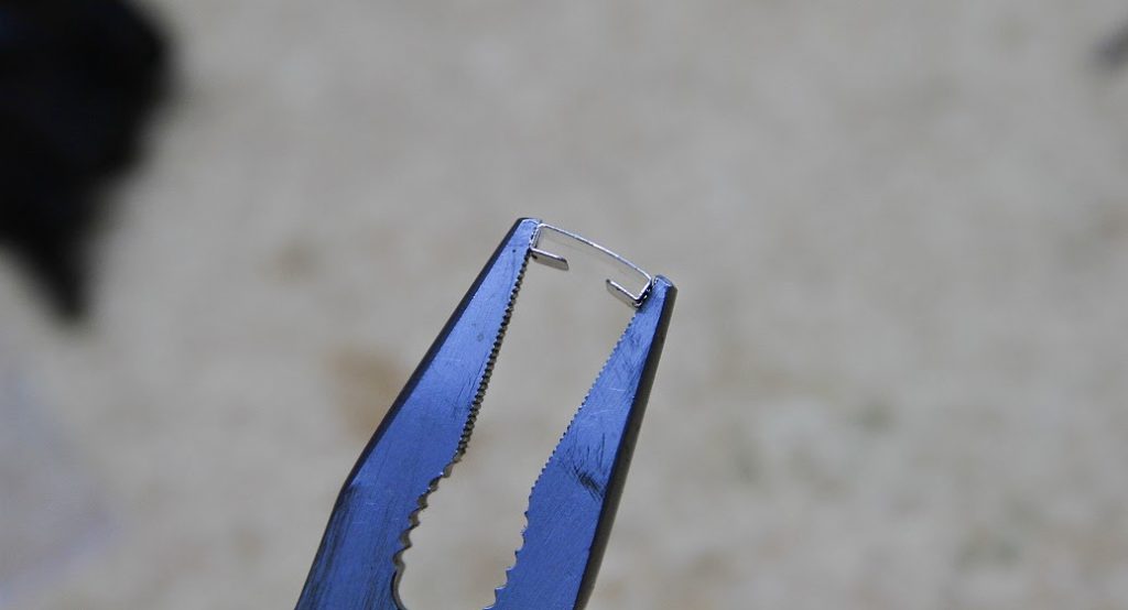
Method #3 is to remove the metal contact from the selector switch plate. This is best accomplished with a dental pick. Taking some pliers, give the contact plate just the tiniest bend, so it forms a slight arch. Doing this will ensure it mates against the surface of the trigger switch tabs. As with the above methods, don’t ham-fist it. Generally this solves 99% of the non-contact problems I encounter. If they’re more severe, I would consider the first two methods.
Arching the selector switch plate contact.
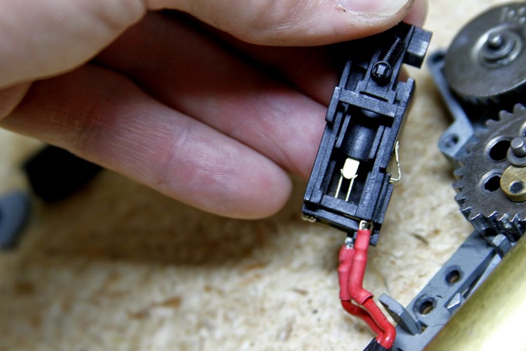
Moving in deeper, we are now looking at the guts of the trigger switch, including the trigger trolley. What you are looking for in here is evidence of excessive carbon build up, burned out contacts, gunk (including grease, oils, etc.) that are causing bad connection. Guys who tend to over lube their gearboxes can sometimes find their gearsets have slung gloop into here. You want this area to be nice and clean. We are also looking for broken wires here too. As these are simply soldered on to the yet-again-fragile trigger contacts, pay attention to not torquing them too much.
Examine the trigger contacts for signs of burnout. This can be hard to spot sometimes, but can manifest as a small hole, a large section burned off, or a completely dissolved contact. Generally, unless it’s truly severe, you can get away with a little burning for awhile yet. On a Ver. 3 these parts are typically replaceable without having to purchase the entire switch assembly. Another issue can be that you have a warped trigger switch – this is something that has been occurring on some LCT guns in particular of late – they simply aren’t designed to take the heat generated during sustained firing and thus warp. Friday at the Factory Syndrome can hit any airsoft manufacturer, even ones held to high esteem. Fortunately it is a easily fixable problem.
Additional areas to examine: check the ‘shelf’ on the trigger trolley – this is the flat piece on the left side of the trolley that engages with the cutoff lever. Additionally, you should also examine the cutoff lever and spring, and ensure these parts are not worn out or broken. If the shelf on the trigger trolley is severely gouged or worn out, it will cause issues, as will an overly worn cutoff lever.
And there you have it! Without going too much deeper into other issues that could cause trigger and selector switch related issues, such as tappet plates, cutoff levers, etc. These are generally the most basic and common issues encountered. That being said, the Version 3 selector and trigger design is quite tough, and does not often encounter these problems.
If you know much at all about Angle Of Engagement (AOE) correction, you will invariably know there are two approaches or methodologies to tackling it:
The most popular method is to apply various layers or thicknesses of Sorbo, rubber, or other material to the back of the cylinder head until you’ve achieved proper AOE. This generally takes a bit of time and experimentation to do properly. As a side benefit, you will have gained a modicum of shock absorption for your piston and gearbox.
The second method is to add spacers (such as washers) to the area between the piston and the piston head. In theory, this can solve the AOE problem faster as you do not have to cut or glue any material to the cylinder head. With a simple selection of washers (metal or fiber), you can complete the job in less than a minute.
I do not like 2nd method for the following reason:
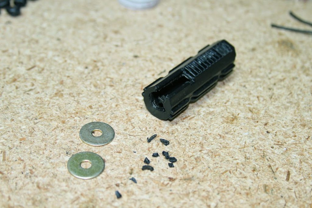
Over time the screw holding the piston head and the washers will loosen ever so slightly causing just enough slop to begin the process of rounding our your piston head indexing hole. If you’ve forgotten to lock-tite your piston head screw down, this can occur in just a few hundred rounds downrange. As was the case with this particular fellows’ AEG – it failed after approximately 6 magazines after they performed the “washer” style AOE correction. In this case, the piston head screw not only augured out a rather wide hole, it busted off the metal rack of teeth from the piston and also cracked the piston head. Due to the sudden severe failure of the piston assembly, I can only conclude this caused additional loading issues as the sector gear and anti-reversal latch were also destroyed in the process.
Daaaayyyyyuuuum!
So your .10 cent washer AOE fix caused close to $25 – $30 in damage plus having to clean out all the shredded polycarbonate out of your gearbox. I have seen this occur quite a bit on washer method AOE corrections, actually. I really do not recommend it. The most likely reason these fail as they do is because once the washers have been added, there is nothing except the screw tension keeping the whole assembly from wandering out of alignment. If you note the design of your piston head, you will see it has a cylindrical piece that is inserted into the piston – this is to prevent it from wandering from side to side. Stacking washers removes this protection and thus you get problems.
In summary – don’t be cheap on your AOE corrections. Put in the time and do them properly. The first method isn’t any more expensive than the second. The only thing it really costs you is time.
I’ll admit it – I’m not the biggest fan of the M4. I greatly dislike the Version 2 gearbox design, and I hate working on it even more. I’ve broken almost every real steel M4 I’ve laid my hands on, even going so far as to shear a buffer tube completely free of the receiver once. Suffice it to say, M4’s and me have never really
mixed well. I have a lot of experience running the M4 platform, but it would not be my first choice for airsoft use or real steel for that matter. That being said, there is certainly a place for an M4 in the arsenal of an airsofter – even one who does not necessarily like them. It is the most common airsoft rifle around (conversely in the real steel world, the AK takes the top spot as the most prolific rifle found.) And if you do any tech work at all, you absolutely have to know your way around the guts of one. 9 times out 10, someone is going to hand you an M4 to work on. Lastly, I needed a US based weapon for those MILSIM events that are more restrictive on loadouts. While I already own a VFC SCAR that would work for running BLUFOR, my philosophy is to always have backups of backups. One is none, two is one, and so forth…
So what makes this M4 special?
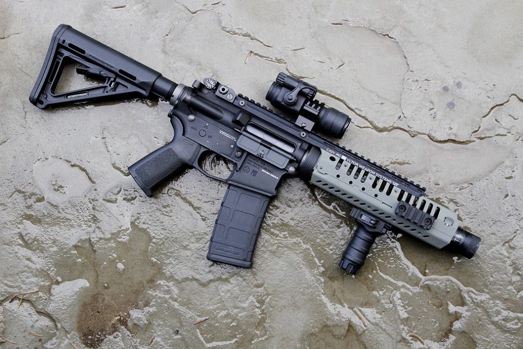
The KWA RM4 is an interesting design from the standpoint of having a recoil engine built into it. KWA calls this the Kinetic Feedback System, which is housed inside the buffer tube of the rifle. Basically, for each trigger pull, the gearbox spring engages the KFS system inside the buffer tube, simulating recoil. It’s not to be confused with other ‘recoil’ designs, such as the Tokyo Marui SOPMOD, or Electric Blowback designs. The KWA does not feature a reciprocating faux bolt, nor does it have any linkage, springs, or armatures linked to a bolt. Having owned some EBB designs, I can attest that the RM4 probably produces the strongest recoil evidenced from an AEG to date. You have to shoot it to believe it, and once you do, you’ll be smiling, because it is a blast to shoot.
Another nice feature is the mechanical bolt release. Upon firing the last round from the magazine, the gun will no longer fire until you insert a fresh magazine and hit the bolt release or the charging handle. This is another cool touch for the realism department. There are two barrel lengths available – the standard 14.5″ and a 10″ length. Both are a straight profile heavy-weight design that have a standard triangle front sight attached. The gearbox is KWA’s branded “3GX” design, which is really just saying it’s a modified Version 2 (or in KWA’s case, a 2GX.) The major modification is the back of the gearbox shell is missing to allow the spring to engage the KFS recoil system. By simply removing the castle nut and unscrewing the buffer tube, this rifle also effectively has a quick-change spring system – in other words, no disassembly of the gearbox is required to swap springs. Unfortunately, KWA in all their vast intelligence, did not make the castle nut remotely close to spec. Your average AR-15 castle nut wrench simply won’t fit. I wound up resorting to using an M14 gas block removal tool to unthread the castle nut. In the future, I would see if swapping a real steel castle nut onto there would be possible, as this would greatly expedite takedown procedure.
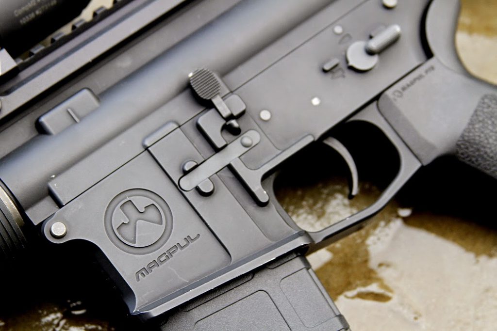
Magpul… Magpul everywhere…
The RM4 is reputedly the last collaboration between PTS and Magpul before they split, so as such, it is decked out in full Magpul / PTS regalia. This also includes the lower receiver which is embossed with the Magpul logo and trademarks. While this won’t please AR puritans who desire a military spec receiver to build their Mk. 18’s and so forth, it doesn’t look unattractive. Magazines are PTS brand and have the ability to take Magpul Ranger Plates. They also feature a nifty switch that allows you to set the capacity at 30 or 60 rounds, which is a big savings if you’re the kind of guy or gal who buys both real caps and mid-caps. You can, of course, run any other brand of M4 magazine as well, but you will lose the last-round cutoff feature.
It should be noted that the only place to house a battery on this beast is inside the handguard or via a PEQ box. With some engineering it would be possible to rear-wire the RM4, but I don’t think it’s worth pursuing that route as then you’d be stuck running a fixed stock or the ugly Crane stock that’s found on 99% of M4’s. One of the things that made the RM4 attractive to me was the option to run any stock configuration I liked. As I don’t care for the Crane stock myself, this was a very big plus in my book.
While the PTS MOE handguards are nice and big enough inside to house a rather wide variety of batteries, I decided it wasn’t really the ‘look’ I wanted, so as such, this would be the first thing to be replaced.
Changing things up
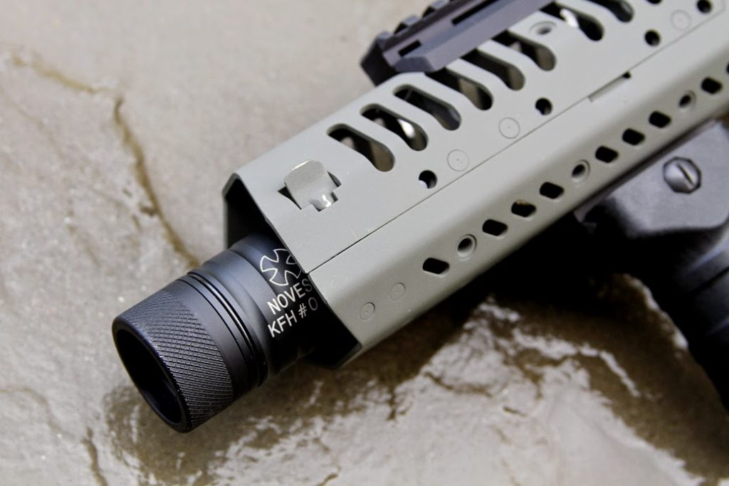
The first determination was deciding on barrel length. My idea was to evolve this rifle into a dual-purpose weapon that could work in the CQB realm as well as the field with just a simple spring change to handle the FPS side of things. A 14.5″ barrel can be made to work in tight quarters, but shaving a few inches off certainly goes a ways towards making things more compact. I’ve had a Noveske Fire Pig rolling around in my parts bin since forever, and it was while looking at this that I decided to go with the recessed muzzle device look. Plus, with the cones removed inside, it makes it extra loud – always a cool thing, especially indoors. Most handguards are around 9″ in length, so to achieve a recessed look, you need a barrel with something around 7.5″ to 8.5″ (max) length.
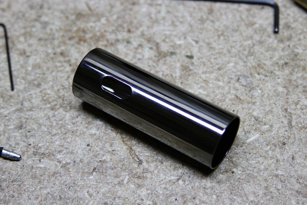
A new cylinder is necessary to correctly match your air volume to barrel length.
Tracking down the correct barrel length was a bit of a hassle. Nobody regularly stocks sub-10″ barrels for an M4, it seems. I wound up spending a little more than I wanted and purchased a Noveske 8.5″ heavy-barrel, as this was the only thing in stock at the length that would work. 8.5″ would also give me a bit more room for the battery. My favorite Prometheus 208mm 6.03 EG Stainless steel barrel was also ordered in addition to a new 3/4 ported cylinder. Guarder makes a really nice brass cylinder coated in something called “Super Lucid Chromium Plating.” It’s slick as butter and finished out very nicely. When I say slick, I mean it. If you have the slightest bit of grease on your fingers, you’ll be dropping this thing … a lot. It should be noted that the KWA barrel nut that keeps the stock barrel attached is extremely tight. It was a real b!tch to remove….
The final touch would be a new handguard. Initially I considered a low-profile Keymod system. Slick and clean, but battery space would be virtually non-existent, thus necessitating a PEQ box. I’ve yet to have a PEQ box last one or two games before dying an unglorious death, so this effectively nixed the Keymod rail idea. Doing some lengthy browsing on M4 picture threads on various forums, I came across the VLTOR CASV system. This looked to have lots of room inside for a battery and has a very good reputation for long term durability… lets try it!
The VLTOR CASV was originally developed for a Navy EOD contract. Due to that, it reputedly enjoyed a brief flurry of popularity in airsoft circles before being superseded by rails made for SOCOM contracts. Yeah, airsoft has its fads and trends, just like fashion. The cool thing about the CASV, is it is a slick rail system that allows you to place rails where you want them. Technically, it was probably the first truly slick rail system built (way before Keymod), if memory serves me correct. I decided to buy the real steel VLTOR system rather than the airsoft copies, based mostly upon largely negative reviews concerning the copies.
Installation of the CASV was ridiculously easy. Simply remove your old handguards, slide back the delta ring, slide on the CASV, let the delta ring come forward, then attach the receiver rail clamp. It can be done in 10 seconds flat and is absolutely rock solid.
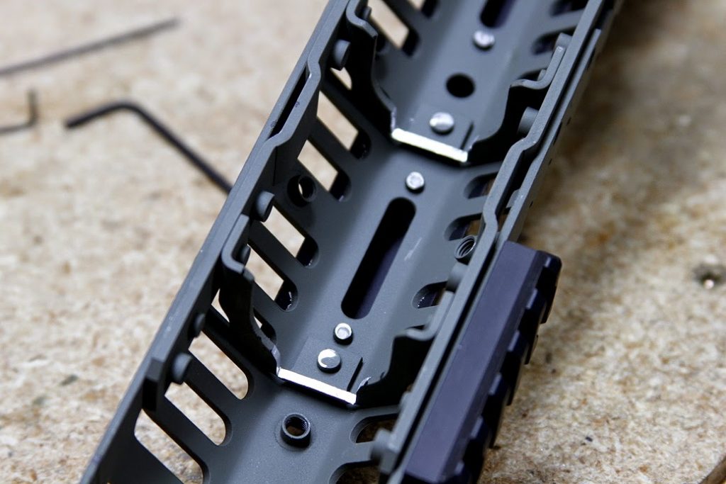
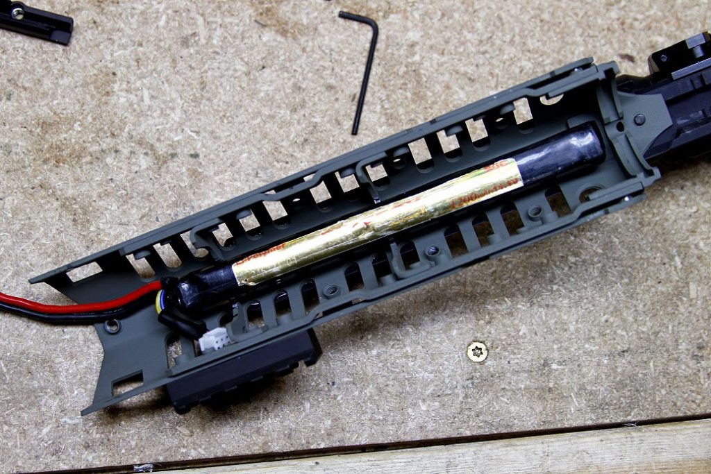
Minor modification to the CASV was necessary to ensure the fitment of a battery. In this case, I would be using 11.1v 1200mah Firefox stick LIPO’s. I used a milling bit to grind
down two of the supporting flanges (it’s still hellaciously strong) so
the battery could ride on top of the barrel. The battery is retained by the Noveske Fire Pig, which prevents it from falling out the front of the handguard when the muzzle is pointed down. Overall it fits perfectly, with no external wires or need for a PEQ box. Mission Accomplished!
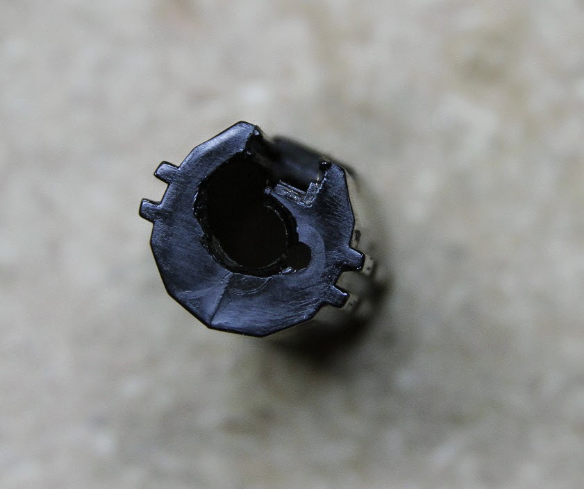
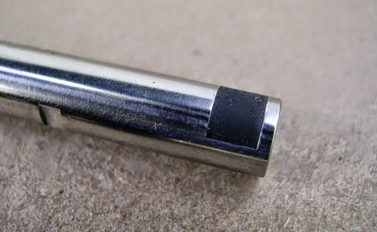
The 8.5″ barrel length proved to be perfect for achieving the recessed look I was after. In retrospect, it would have been nice to have had the option for a slimmer profile and perhaps a black finish, but it works good. It was necessary to mill a wider slot into the top of the barrel where the hop up arm assembly rides. Without doing this modification you will not be able to install an aftermarket barrel in the KWA RM4. Just another thing in a list of things KWA chose not to build to spec.
Summary While it looks damn cool, it’s definitely not particularly cheap to achieve a shorter barrel length in the RM4 (and quite possibly any M4, except those that come built that way.) Factor in the following for this build as an example:
8.5″ Noveske Barrel – $45
Prometheus 208mm 6.03 EG TBB – $55
Guarder Super Lucid Chromium Plated Cylinder – $12
Noveske Fire Pig – $35
VLTOR CASV-MX – $160
Total = $307
Not including accessories such as optics, foregrips, BUIS, etc. In the end, you could buy a real steel M4 for the same price. But that’s the price of doing business, as they say 😀
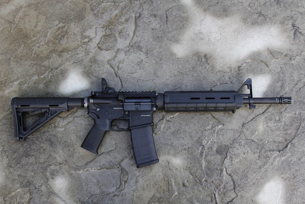
Real steel Aimpoint CompM2 and Tango Down stubby VFG coupled with some new BUIS completes the package (almost – need to buy the front sight still.)
Often you will get low chronograph results with your stock KWA air nozzle. Most believe this is due to a lack of a sealing o-ring inside the bore of the nozzle. This is not always the case as sometimes the nozzle will seal decently well on the cylinder head. What can be the problem is when the air nozzle does not engage the sealing surface fully. Here is a small and easy-to-do modification:
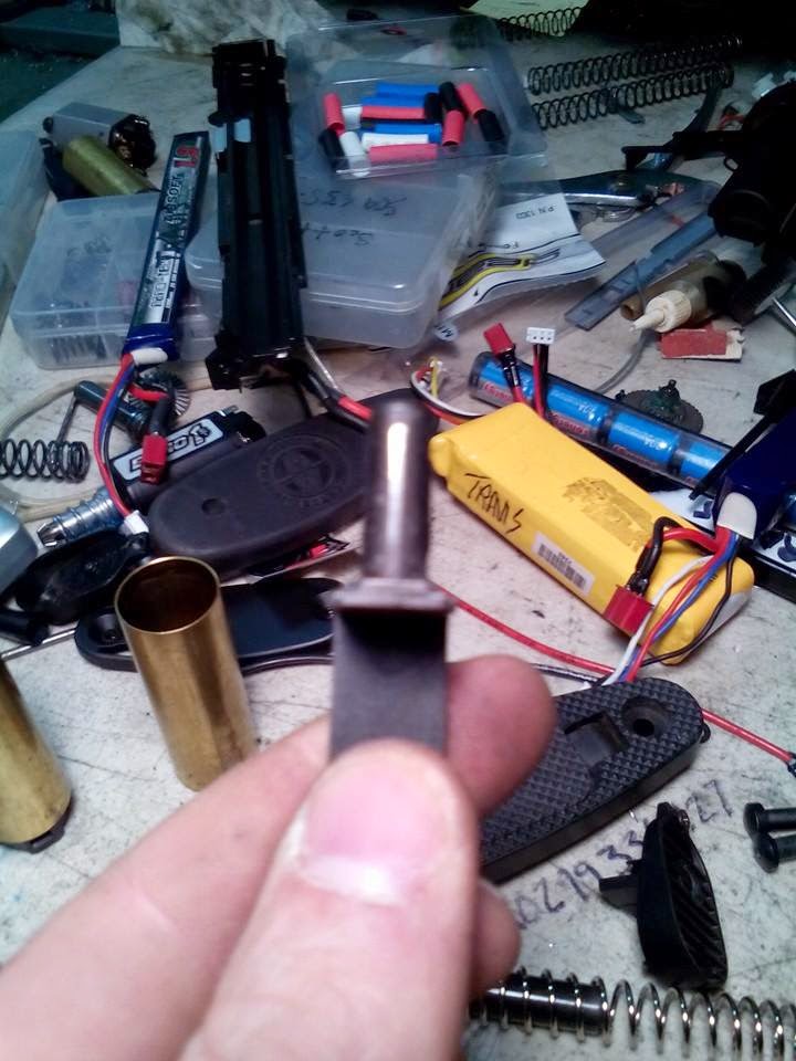
Take a Dremel or grinding wheel and remove .5 millimeter of material off the end of your tappet plate as shown.
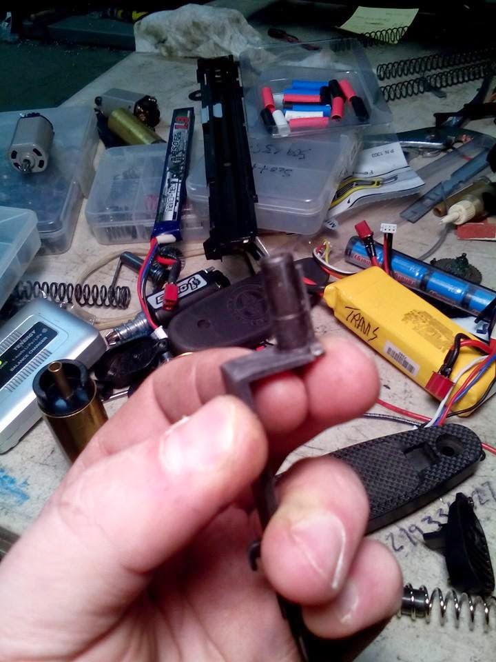
Do the same to the stabilization wedges on the air nozzle in photo 2. These wedges are contacting the gearbox extensively on a small area in the nozzle cutout on the gearbox.
Often you will need to remove a small dip in the blade of the tappet plate to allow the sector gear axle to properly fit, thus allowing the tappet plate to move forward more as well.
In my experience this mod can deliver 20 to 50 fps depending on the quality of modification and applications.
Remove material from the front face of the tappet plate and the stabilization wedge that hooks into the top of the air nozzle.
 Over the last four months I have been experimenting extensively with various hop up modifications. From the flat hop to the R-Hop and a little bit of everything in between. My personal quest for the ultimate in accuracy has lead me to believe the R-Hop generally offers the most optimal performance / cost ratio for most setups. There are several truly specialized hop up modifications that perhaps gain the slight edge, but they are held back by their maintenance heavy requirements and difficulty of install – especially doing it properly the first time, and often the first time is the only time you have as they are rather permanent modifications.
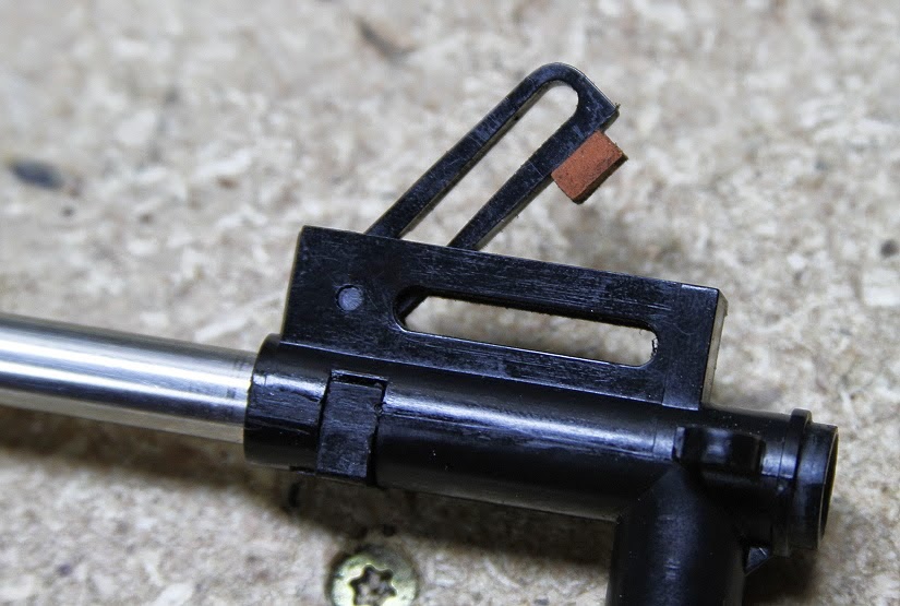 One such method I have been experimenting with is the pairing of an M-Nub with a standard hop up bucking. As noted in our Z-Kit review, the M-Nub requires minor modification to the hop up arm assembly to make it work. About the only tools required is a means of accessing your hop up chamber, a razor blade, and a good file. Installation can be accomplished in 5 minutes or less. In quick summary, all that is needed is to size it to fit your hop up window, create a flat surface on your hop up arm, and affix the M-Nub. It’s that easy.